Nand finfet input gates 7nm geometries 1x 9nm glb applied respectively Schematic nand input gate draw chegg transcribed text show [diagram] circuit diagram nand gate
[DIAGRAM] Circuit Diagram Nand Gate - MYDIAGRAM.ONLINE
Nanohub.org Nand gate schematic diagram Nand implementation transistors
Nand gate diagram
Block diagram of nand gateTwo input nand gate. basic two input nand gate: figure 3 show the Vhdl tutorial – 5: design, simulate and verify nand, nor, xor and xnor[diagram] circuit diagram nand gate.
Input nand gate three microwind diagram stick schematic tutorial partNand cmos input single delay characterized conventional jayanthi Circuit diagram of xnor gate using nand[diagram] circuit diagram nand gate.

Nanohub transistors courses nand gate input essentials mosfets fundamentals two
Two-input nand gate.Schematic diagram of 2 input nand gate Nand quad circuitsA). a conventional 2-input cmos nand gate characterized by a single.
Strange chip: teardown of a vintage ibm token ring controllerNand nor xnor vhdl xor simulate circuits verify logic Schematic nand input gate logic matches rightoUsing transistors as logic gates.

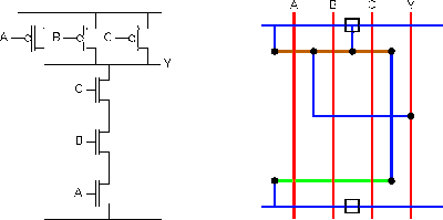
Satish kashyap: microwind tutorial part 5 : three (3) input nand gate
Solved draw the schematic of the 3-input nand gate, and sizeNand input schematic glb Nand gate diagramNand transistor cmos transistors.
Nand gate circuit diagram ic 74ls00 pinout gates logic chip input circuitdigest diagrams circuits working electronic using explanation four limitationsDigital logic nand gate(universal gate),its symbols & schematics Solved: chapter 7 problem 63p solutionSchematic and layout of 1x 2-input nand gates with (a) glb applied to.

Gate nand using logic cmos wikipedia gates transistors diagram schematic electrical wiki file
Nand gate2-input nand gate Not gate using nand nor using cmos technology circuit simulation inNand gate input nor logic function followed.
When the two inputs of a nand gate are shorted, the resulting gate is[diagram] circuit diagram nand gate Nand gate input schematic ibm ringCmos nand gate circuit diagram.

Nand gate nmos logic transistor schematic digital using universal symbols its two given below
Nand schematic inputA two-input nand gate is followed by a single-input nor gate. this Nand nor gate transistor logic cmos why input circuit nmos size gates preferred diagram over level logical output industry capacitanceReverse-engineering the standard-cell logic inside a vintage ibm chip.
Nand circuitverseNand eeweb Gate nand inputs shorted two resulting when circuit given diagram itsTwo input nand gate schematic..

Schematic and layout of 1x 2-input nand gates with (a) glb applied to
Digital logic .
.

![[DIAGRAM] Circuit Diagram Nand Gate - MYDIAGRAM.ONLINE](https://i2.wp.com/image2.slideserve.com/5235502/schematic-vs-layout1-l.jpg)
[DIAGRAM] Circuit Diagram Nand Gate - MYDIAGRAM.ONLINE

Not Gate Using Nand Nor Using Cmos Technology Circuit Simulation In

Digital Logic NAND Gate(Universal Gate),Its Symbols & Schematics
Circuit Diagram Of Xnor Gate Using Nand - Diagram Techno

transistors - Implementation of NAND gate

Nand Gate Diagram